光纤分布式传感设计翼形变形的设计验证
Josiah费用

In response to government initiatives such as the FAA’s Continuous Lower Energy Emissions and Noise (CLEEN) program, aircraft manufactures are working on new technologies to increase efficiency and reduce noise. The design of a morphing wing leading edge is one method that can be used to accomplish these goals. Traditionally, slats are used to increase the angle of attack of a wing for take-off and landing. Unfortunately, since there is a gap between the slats and the wing, they produce a substantial amount of turbulence and noise. With a morphing leading edge, the angle of attack is increased smoothly by deforming the wing via internal actuators. This gives the air a continuous surface to flow over, which helps decrease turbulence and noise production. The morphing wing’s leading edge is made with an elastomeric material that must be sufficiently compliant to change shape to a specific geometry during landing and take-off, and yet, rigid enough to maintain that geometry when subject to loads associated with inflight conditions.
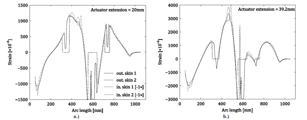
In a paper published at the recent AIAA SciTech Conference, researchers from Delft University of Technology and the Fraunhofer Institute for Building Physics designed, manufactured and tested a functional, seamless, morphing leading edge demonstrator built with an actuator mechanism and an aero-elastic airfoil skin. An analysis of predicted strain was done using a (FEM) analysis tool and results were compared to experimental data acquired with Luna’sodisi.B分布式光纤传感系统。为了使变形的前缘可行的安全飞行,所以必须由翼型弯曲而不是拉伸来引起的变形。因此,研究人员重要的是沿着翼型的周边测量连续应变型材。光纤传感器沿着翼型的内部和外侧排列,以便区分轴向和弯曲菌株。应变分析表明,一旦内部应变被否定,沿箔的内部和外部的应变值几乎相同。这表明翼形变形实际上是由于弯曲,验证了他们的设计原则。


These types of measurements are not practical with traditional point sensing methods that cannot provide the degree of resolution needed by design engineers who work on cutting edge technology with a high degree of unknowns. The ODiSI B, based on Rayleigh Backscattering technology, is capable of using a sensor constructed of unaltered fiber optic cable and can provide high density strain measurements down to 1.28 mm spatial resolution and with a 20 meter maximum sensing length. The ODiSI B has four user selectable operating modes that optimize sampling rate, sensor length and spatial resolution according to the test requirements. Data captured with the ODiSI B can be viewed real time or captured for post processing and data analysis. For more information the full paper can be accessedhere。参考:J. Sodja,M. Martinez,R.Beuker,J.Impson,“Experimental Evaluation of the Morphing Leading Edge Concept”, Proceedings of the American Institute of Aeronautics and Astronautics Science and Technology Forum 2015, June 2014.